
SYSTEM 09 | PROCESS RELIABILITY SYSTEMS
Magnetic Separator Medium Loss Monitoring
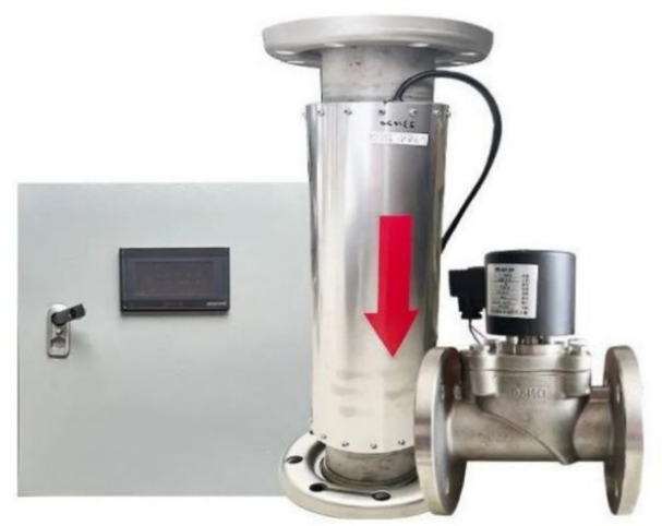
Medium loss at the magnetic separator tailings remains one of the least measured causes of magnetite consumption in coal washeries. John Finlay’s Magnetic Separator Medium Loss Monitoring System provides continuous, real-time measurement of magnetite loss, helping operators identify losses early, optimize recovery performance and reduce medium consumption costs.
±0.1%
Accuracy
0–100 g/L
Measuring Range
0.01 g/L
Resolution
DN100 / 150 / 200
Nominal Bore
DEFINITION & OVERVIEW
What is Magnetic Separator Medium Loss Monitoring?
Magnetic separator medium loss monitoring measures, continuously and in real time, how much magnetite is escaping in the magnetic separator's tailings stream the single largest and least visible loss point in a dense medium circuit's magnetite consumption.
An electromagnetic induction sensor installed directly in the tailings line reads magnetite concentration continuously. Paired with a clean water flowmeter at the demagnetising screen spray, the system calculates actual medium loss rate, not just a concentration reading the two numbers together are what turn a sensor output into a real production metric.
This closes a gap most washeries have lived with for years: recovery loss at the magnetic separator is well understood as a cause of high magnetite consumption, but almost never measured directly. Most plants infer it indirectly from monthly purchase records long after the loss has already happened.
How It Works
Electromagnetic induction sensor reads magnetite concentration in the tailings stream continuously, paired with a clean water flowmeter to compute real loss rate.
Automatic Zeroing
A motorized ball valve runs a scheduled zero cycle, holding calibration without manual intervention.
Role in DMS Circuit
Feeds a 4–20 mA isolated signal directly into the plant's density control and SCADA layer alongside other circuit instrumentation.
Parameter | Value |
|---|---|
Principle | Electromagnetic induction |
Measuring Range | 0 – 100 g/L |
Accuracy | ±0.1% |
Measuring Resolution | 0.01 g/L |
Minimum Sensitivity | 1 g/L |
Output | 4–20 mA, isolated |
Power Supply | 220 V AC, ≤60 W |
Nominal Bore | DN100 · DN150 · DN200 |
Automatic Zeroing | Motorized ball valve, scheduled zero cycle |
KEY FEATURES
Key Features & Performance Highlights
System 09 is built to give a stable, trustworthy number on a measurement most plants have never attempted to instrument directly.
Ultra-Stable Circuit with Temperature Compensation
An ultra-stable integrated circuit with temperature compensation and waveform correction holds accuracy across normal plant temperature swings, the reading stays trustworthy through a full shift, not just at calibration.
Automatic Zeroing
A motorised ball valve runs a scheduled zero cycle automatically, removing the manual recalibration routine that most concentration instruments depend on to stay accurate over weeks of continuous duty.
Paired Flow Reading for Real Medium Loss
Concentration alone isn't loss. Pairing the sensor with a clean water flowmeter at the demagnetizing screen spray converts a concentration reading into an actual medium loss rate, the number that connects directly to cost.
WORKING PRINCIPLE
How Medium Loss Monitoring Works in the Circuit
Understanding the measurement chain helps process engineers see exactly what number they’re getting and where it comes from.
Sensor Installation
A DN100, DN150 or DN200 electromagnetic induction sensor is installed directly in the magnetic separator's tailings line.
Continuous Concentration Reading
The sensor measures magnetite concentration continuously across a 0–100 g/L range at ±0.1% accuracy.
Scheduled Auto-Zero
A motorized ball valve runs a scheduled zero cycle to prevent long-term drift, without operator intervention.
Paired Flow Calculation
Concentration is combined with a clean water flowmeter reading at the demagnetizing screen spray to calculate an actual medium loss rate, not just a concentration figure.
Signal Output
A 4–20 mA isolated output feeds the result directly into the plant's density control and SCADA layer for logging and alarming.
TECHNICAL SPECIFICATIONS
Magnetic Separator Medium Loss Monitor | Full Specification
Specifications sourced directly from John Finlay’s instrumentation documentation.
Parameter | Specification |
|---|---|
Principle | Electromagnetic induction |
Measuring Range | 0 – 100 g/L |
Accuracy | ±0.1% |
Measuring Resolution | 0.01 g/L |
Minimum Sensitivity | 1 g/L |
Output | 4–20 mA, isolated |
Power Supply | 220 V AC, ≤60 W |
Nominal Bore | DN100 · DN150 · DN200 |
Automatic Zeroing | Motorized ball valve, scheduled zero cycle |
COMPARISON
Manual vs. Unmanned Medium Addition
With System 09
Without Direct Monitoring (Most Plants)
Benefits for Coal Washeries
Applications of Medium Loss Monitoring
System 09 is most valuable wherever magnetite consumption has been difficult to explain using purchase records alone.
Diagnosing Magnetite Consumption Gaps
Directly measures the loss point our own diagnostic framework identifies as usually the largest single cause of high magnetite consumption.
Retrofitting Existing Separators
magnetic separator tailings lines without requiring a separator replacement.
Correlating Loss with Maintenance Timing
Continuous trend data shows whether loss increases as drum wear or separator condition changes over time.
SCADA-Integrated Density Control
4–20 mA output integrates directly into existing automation layers alongside density and process control instrumentation.
Coking Coal Washeries with High Magnetite Turnover
High-consumption circuits get the fastest payback from finally being able to see where the magnetite is actually going.
Post-Commissioning Circuit Verification
Confirms a newly installed or serviced magnetic separator is actually recovering to its rated efficiency.
About John Finlay
Medium Loss Monitoring Supplier in India
Why John Finlay?
Process-Focused Instrumentation
Every measurement system is selected to solve a real operational challenge within coal preparation plants.
Proven Dense Medium Expertise
John Finlay’s instrumentation solutions are designed specifically for dense medium circuits, magnetic separator recovery systems and plant optimisation projects.
Integrated Automation Solutions
All systems are designed for seamless integration with plant SCADA, PLC and process control infrastructure.
Local Engineering Support
Installation, commissioning and after-sales support are delivered through John Finlay India’s engineering team.
Magnetic Separator Medium Loss Monitoring | Frequently Asked Questions
Common questions from coal washery process engineers evaluating direct medium loss instrumentation.
It measures magnetite concentration in the magnetic separator’s tailings stream in real time, using electromagnetic induction. Paired with a clean water flowmeter at the demagnetizing screen spray, it calculates an actual medium loss rate rather than just a concentration reading.
The sensor holds ±0.1% accuracy across a 0–100 g/L measuring range, with 0.01 g/L resolution and a minimum sensitivity of 1 g/L, aided by an ultra-stable circuit with temperature compensation and waveform correction.
No, a motorized ball valve runs a scheduled automatic zero cycle, holding calibration without operator intervention.
The sensor is available in DN100, DN150 and DN200 nominal bore to match your tailings line.
The unit outputs an isolated 4–20 mA signal that integrates directly into your existing density control or SCADA layer alongside other circuit instrumentation.
Understand Where Your Magnetite Is Being Lost
Real-time medium loss monitoring provides the visibility needed to reduce consumption, improve recovery efficiency and make informed operational decisions.
Talk to an ExpertRelated Equipment
Dense Medium Separation
Magnetic Separators | LF-HMDS wet drum separators with recovery efficiency up to 99.9%.
Blog
Magnetite Consumption Benchmarks | The diagnostic framework this instrument makes directly measurable.