Turning Waste Rock into Revenue: $9.21 Million Annual Benefit
Turning Waste Rock into Revenue: $9.21 Million Annual Benefit
Turning Waste Rock into Revenue: $9.21 Million Annual Benefit Read More »
John Finlay Group Of Companies

Turning Waste Rock into Revenue: $9.21 Million Annual Benefit
Turning Waste Rock into Revenue: $9.21 Million Annual Benefit Read More »
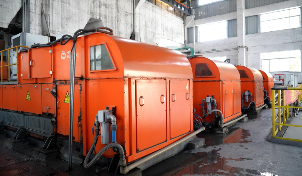
Lead-Zinc Ore Sorting at Fankou Mineral Processing Plant
Lead-Zinc Ore Sorting at Fankou Mineral Processing Plant Read More »
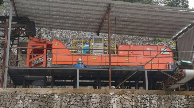
HPY ore sorters achieved a 4.29x enrichment ratio in the first commercial molybdenum ore sorting application, rejecting 77.56% of feed at Yulong Mine.
First Commercial Molybdenum Ore Sorting Application – Yulong Mine Read More »
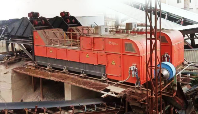
Recovering Value from Waste Rock: White Roach Molybdenum Case Study
Recovering Value from Waste Rock: White Roach Molybdenum Case Study Read More »
Molybdenum Ore Sorting Case Study: 42% Waste Rejection with 86.1% Recovery Circle Series Pre-Concentration at Hengyu Molybdenum Mine Luanchuan Hengyu Mining Co., Ltd. operates the Hengyu Molybdenum Mine, a 6,500 t/d operation that processes ore with a raw grade of just 0.046% molybdenum. At that grade, every ton of waste rock that reaches grinding and flotation carries a real cost in power, reagents, and tailings capacity spent on material that will never yield metal. John Finlay delivered this cost installation, fitting four Circle Series sorters to pull that waste out before it gets there. Project Overview Operator Luanchuan Hengyu Mining Co., Ltd. Site Hengyu Molybdenum Mine Ore Type Molybdenum Feed Material +10–45mm, raw ore grade 0.046% Mo Processing Capacity 6,500 t/d Challenge Low-grade ore means most run-of-mine tonnage is waste; sorting it out before grinding and flotation protects downstream capacity and reagent cost Solution Four Circle Series ring-shaped sorters were installed to pre-concentrate the +10–45mm fraction ahead of the beneficiation circuit, rejecting barren rock while holding onto the mineralized fraction for further processing. Equipment and Performance 1. Sensor-Based Pre-Concentration● Machines Used: Machines Used: Four Circle Series C1500 units● Processing Capacity: 6,500 t/d● Function: Removes low-grade waste rock from +10–45mm feed ahead of grinding and flotation Sorting Results ● Raw Ore Grade: 0.046% Mo● Concentrate Grade: 0.079% Mo● Waste Rock Grade: 0.018% Mo● Rejection Rate: 42%● Recovery Rate: 86.1%● Enrichment Ratio: 1.72 Benefits and Outcomes ● Economic Efficiency: Rejecting 42% of feed before grinding and flotation cuts the tonnage those downstream stages need to process, lowering power and reagent cost per tonne of contained molybdenum recovered. ● Environmental Impact: Waste rock pulled out at the sorting stage reduces the volume reaching tailings storage. ● Operational Efficiency: Lifting ore grade from 0.046% to 0.079% before flotation, a 1.72x enrichment, gives the downstream circuit a more consistent, higher-grade feed to work with. Conclusion At Hengyu, four Circle Series sorters turn a low-grade 0.046% Mo ore body into a workable feed by rejecting 42% of run-of-mine tonnage while holding 86.1% of the contained molybdenum. The result is a 1.72x grade lift before the ore ever reaches flotation, the kind of pre-concentration that makes marginal-grade deposits easier to run economically. Considering pre-concentration for a molybdenum, copper, or polymetallic operation? Talk to John Finlay’s ore sorting team about a feasibility assessment for your ore body. Request a Feasibility Assessment
Molybdenum Ore Sorting Case Study: 42% Waste Rejection with 86.1% Recovery Read More »
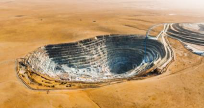
How Sensor-Based Ore Sorting Generated $31.5 Million Annual Benefit at Jindi Molybdenum Mine
Your washery loses 15–25% of coal every day to the slurry pond. Here’s how four Indian mines recovered it and why the engineering matters. Every Indian coal washery faces the same problem Every Indian coal washery faces the same problem: coal loss in the slurry pond. At a typical SECL or BCCL washery processing 1,000 tonnes per day, that’s 150–250 tonnes of coal disappearing daily. Over a year, that’s 55,000–90,000 tonnes of coal worth ₹4–7 crore in lost revenue. And that’s before counting the cost of managing tailings, extending pond life, and grinding ore further downstream to make up for lost coal. Most washeries accept these losses as inevitable. The dense media cyclone captures what it can, but the fine coal fraction (-1 mm) and near-gravity material escape. Heavy media bath loses magnetite. Flotation cells clog. Until now, the engineering toolset hasn’t really changed in 30 years. But what if 98% recovery were possible? Not theoretical. Not after massive capex. But in 18 months, using existing equipment at four operating mines across India, two in Chhattisgarh, one in Jharkhand, and one in Odisha, this is what sensor-based dry coal sorting achieved. This is what sensor-based dry coal sorting achieved. And the implications shift how you think about coal beneficiation economics. How loss happens Traditional washery loss occurs at three points. Dense media cyclones work on density difference, but coal density overlaps with gangue (near-gravity material). About 5–10% of coal reports to the waste stream. Desliming screens remove fine material, but −1mm coal is economically valuable in power plants and coking; it shouldn’t go to tailings. Flotation cells recover some coal, but when the ash content exceeds 30%, which is common in Indian ROM coal, flotation efficiency declines. The root cause: You’re asking chemistry (flotation, dense medium density) to do what physics (X-ray density imaging, machine vision + air jet precision) does better. Your washery is good at bulk separation, but it is not designed for fine, near-gravity sorting. This limitation is not designed for fine, near-gravity sorting. This is why recovery plateaus at 85–88% at most coal washeries in India, even well-run ones. The sensor-based solution Sensor-based dry coal sorting combines three technologies. Sensor-based dry sorting combines XRT imaging, machine vision and pneumatic separation to identify coal and gangue in real time. XRT imaging: X-ray transmission scans each coal lump (−50mm to +300mm) at 1.5 millisecond intervals. XRT detects density differences as small as 0.05 g/cm³, separating coal (1.2–1.5 g/cm³) from gangue (2.6+ g/cm³) and magnetite (5.0+ g/cm³) with a precision a dense media bath can’t achieve. Machine vision: HD and 8K cameras capture surface features, color, and texture. This combination catches coal that XRT alone might miss (oxidized surfaces, coal-like mineralization). Two imaging modes together improve accuracy from 92% to 99.5%. AI-assisted identification improves sorting accuracy by combining density analysis with machine vision. AI algorithm: A convolutional neural network (the Wenshu algorithm in HPY systems) processes XRT + vision data in real-time, predicting coal vs. gangue vs. magnetite for each particle. This model learns from each sample, improving over time as the washery operator feeds it data. Separation: Pneumatic air jets, calibrated to particle size, eject the waste stream in real-time. No slurry, no water loss, no density-dependent compromise. Key spec: Response time is 1.5 milliseconds. Belt speed allows ~220 tonnes/hour capacity on a standard-width sorter. This fits into existing washery flowsheets. Four case studies: Real data Case 1: SECL Washery, Chhattisgarh (Coal India) ROM coal grade: 45% ash (typical high-ash CIL coal). Recovery target: −1mm coal fraction currently reporting to tailings. Installed: XRT dry sorter, 200 t/h capacity.After 12 months: Coal recovery improved by 5.2% of feed (translates to ~10,400 tonnes/year for a 500 t/d washery). Tailings pond life extended by 18 months (1.3M cubic meters saved). Equipment wear was recovered in Capex: reduced due to smaller tailings volume and less stress on desliming screens.Economic impact: Coal recovered is valued at ~₹52 lakh/year. Capex: ₹2.5 crore, payback ~4.8 years. This figure excludes tangible benefits from reduced pond management. Case 2: BCCL Washery, Odisha (Captive Coal) Coking coal has lower ash (~32%), but the fine fraction is rich in coal. Recovery metric: Gangue-in-coal reduction (target: <1%).Results: Gangue in coal was reduced from 3.2% to 0.8% in the -10 mm fraction. Flotation cell washout time reduced by 40% (downstream benefit: less scrap, faster cycle). Magnetite recovery improved: 15% less magnetite loss in tailings.Economic impact: Coking coal grade premium recovered. At CIL captive pricing, this initiative results in a value uplift of ~₹38 lakh/year. Payback period is ~6 years, including O&M. Case 3: MCL Washery, Jharkhand (ROM Coal) High near-gravity material (NGM) coal has a density that overlaps with that of carbonaceous shale. Traditional washery: NGM reports to waste (20% of feed by weight). A dry sorter was applied to the -50 mm + 10mm fraction.Results: NGM partitioning accuracy: 88% of coal recovered from NGM-rich stream. Clean coal yield: +3.1% of feed. Water usage in dense media bath: reduced by 12% (lower volume of ore needing beneficiation).Economic impact: ₹44 lakh/year coal recovery value. Reduced water cost (important in Jharkhand water-stressed regions). Case 4: CCL Washery, West Bengal (Central Coalfields) Old washery (commissioned 1987): heavy media cyclone struggling with washability variability. Problem: Frequent changeover in ore source → recovery swings 80–85% depending on geology. Installed an XRT sorter upstream of the cyclone as a pre-concentration step.Results: Recovery stabilized at 92–95% regardless of ore source. Cyclone efficiency: improved (receiving pre-concentrated feed). Operator variance eliminated (machine vision removes subjectivity).Economic impact: ₹31 lakh/year improved recovery. Stability benefit: reduced process downtime during source changes (~5–7 days saved per year per changeover). Typical integration of sensor-based dry sorting into an existing coal beneficiation circuit. Why this engineering works for Indian coal Three reasons dry sorting hits harder in India than globally. First, CIL coal averages 35–45% ash, and this ash is dispersed (not layered), making density-based separation imperfect. XRT sees atomic number (coal is C; gangue is Si/Al), not just density. This is a structural advantage
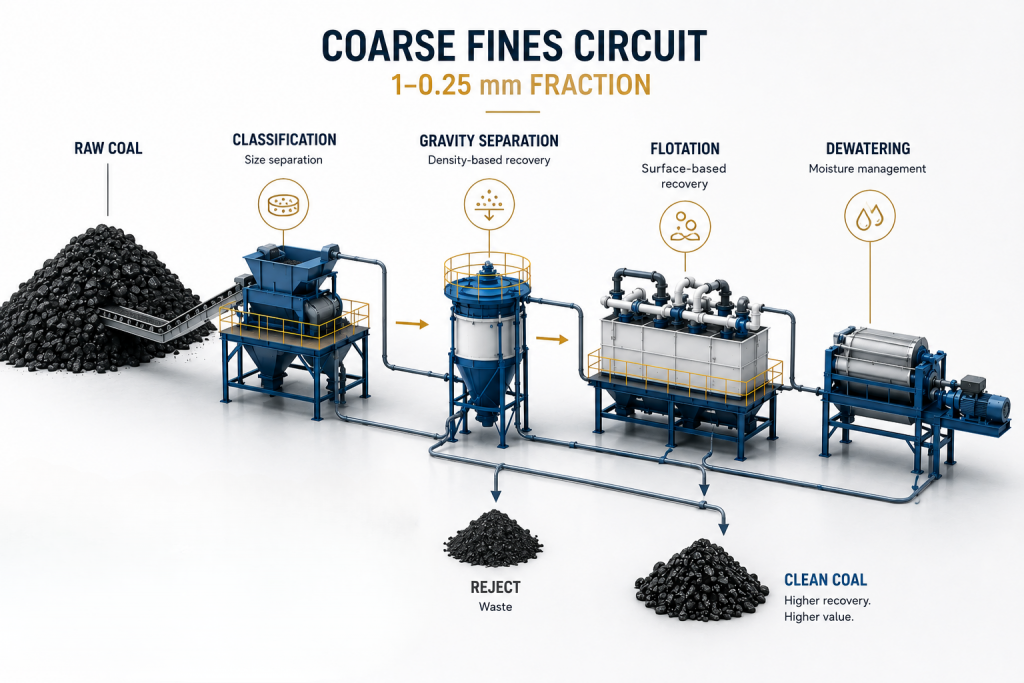
A technical perspective on coarse fines separation, project economics, and circuit selection in Indian coal beneficiation There is a renewed debate in the Indian coal processing industry around the 1–0.25 mm fraction — often called the “coarse fines” fraction. The argument usually follows a simple line:Indian washeries are leaving yield on the table in this size range. HydroFloat coarse-particle flotation can recover that yield. Therefore, Indian operators are commercially behind for not adopting it. The first part of that argument is directionally correct. The 1–0.25 mm fraction is important, and in many washeries it deserves more attention than it receives. The conclusion, however, is too simple. The correct question is not“Why has India not adopted HydroFloat?” The correct question is:“For this coal, this size distribution, this NGM profile, this oxidation condition, this existing circuit, and this capital envelope, which separator gives the best project economics?” That is a very different engineering question. Our group has executed 130+ EPC washery projects globally and currently operates 47 plants. Across Indian, Chinese, Australian, and African coals, the 1–0.25 mm fraction has repeatedly proven to be one of the highest-leverage areas in washery design. But it is also one of the easiest areas to oversimplify. The technology decision should be made on physics, operating data, and full-circuit economics — not on the comparative sales narrative of any single equipment supplier. By Aadil KeshwaniManaging Director, John Finlay India Pvt. Ltd. 1. The Yield Math Needs the Right Denominator A commonly repeated claim is that a 2–3% additional recovery in the 1–0.25 mm fraction can translate into 20,000–30,000 tonnes of additional clean coal per year in a 1 MTPA washery. That number needs careful qualification. A 1 MTPA washery does not process 1 million tonnes per year of 1–0.25 mm material. In many Indian coking coal washeries, this fraction is typically a minority of total ROM feed. The exact number depends on top size, crusher product, seam characteristics, friability, and fines generation. Therefore, a recovery improvement inside the 1–0.25 mm fraction cannot be directly treated as the same percentage improvement in total plant yield. For example, if the 1–0.25 mm fraction represents around 15–25% of total feed, then even a meaningful recovery improvement within that fraction translates into a much smaller plant-level uplift. This does not mean the gain is unimportant. A one-percentage-point improvement in overall clean coal yield can be very valuable in the right plant. But the commercial case must be built on the corrected denominator. The honest calculation is:fraction mass × realistic recovery improvement × clean coal valueminus incremental CapExminus incremental OpExminus operating risk That is the calculation that matters. If a technology claims 2–3 percentage points of total plant yield improvement, then it should be supported by plant data. If the claim is 2–3% improvement within the coarse-fines fraction, then the plant-level gain is much smaller. This distinction is not academic. It determines whether the payback is compelling, marginal, or uneconomic. 2. Coarse-Particle Flotation Works — But It Has Physical Limits HydroFloat is good engineering. The principle of fluidised-bed coarse-particle flotation is sound. By reducing turbulence in the bubble-particle contact zone, the technology can extend flotation beyond the range where conventional mechanical cells become inefficient. In the right mineral systems, this is a powerful advantage. But coarse-particle flotation is still limited by bubble-particle stability. As particle size increases, the forces that detach a particle from a bubble rise faster than the forces holding the particle to the bubble. HydroFloat reduces turbulent detachment, but it does not eliminate gravity, inertia, particle shape effects, incomplete liberation, or surface oxidation. In practical coal terms:Below 1 mm, HydroFloat can perform well on liberated, hydrophobic coal. Between 1.0 and 1.5 mm, performance becomes more coal-specific. Above that range, recovery is increasingly dependent on liberation, density, surface condition, and particle-bubble stability. This does not make HydroFloat ineffective. It simply means the technology should not be treated as a universal answer for the full 1–0.25 mm coal fraction. For coal, the right comparison is not HydroFloat versus a poorly operated legacy fines circuit. The right comparison is HydroFloat versus a properly specified gravity circuit: TBS, Reflux Classifier, small-diameter dense medium cyclone, or a combination of these. That comparison is much closer. 3. Reagent OpEx Cannot Be Treated as a Footnote Any flotation-based circuit has a reagent dependency. In Indian coal, that dependency matters. A HydroFloat circuit requires collector, frother, conditioning, reagent dosing, air supply, froth handling, instrumentation, and additional operating attention. These are not minor items when the incremental yield gain is being measured against only a fraction of total plant feed. The reagent cost may be manageable in some applications. But it must be included honestly in the economic model. Indian coking coal adds another complication: variable oxidation. Coal that has been stored, weathered, blended across seams, or exposed to monsoon conditions can show significant variation in surface hydrophobicity. As oxidation increases, flotation response becomes less predictable and reagent consumption can rise materially. This is one of the recurring reasons why flotation circuits in Indian coking coal do not always achieve design recovery in sustained operation. Gravity circuits are not immune to poor operation. They require classification discipline, water balance, density control, and mechanical maintenance. But their failure modes are different. A TBS, Reflux Classifier, or dense medium cyclone does not require the coal surface to remain consistently hydrophobic. It separates primarily on density and settling behavior. That distinction matters in India. 4. The CapEx Comparison Must Be Scope-Based The capital comparison also needs to be made carefully. A HydroFloat installation for this duty is not just a cell. The installed system may include classification, conditioning tanks, reagent storage and dosing, air systems, froth pumps, launders, instrumentation, civil works, and downstream dewatering modifications. Depending on site conditions and import content, the installed cost can be materially higher than a TBS circuit and often higher than a Reflux Classifier circuit. That does not automatically make HydroFloat uneconomic. If the yield gain is large enough, the payback can justify
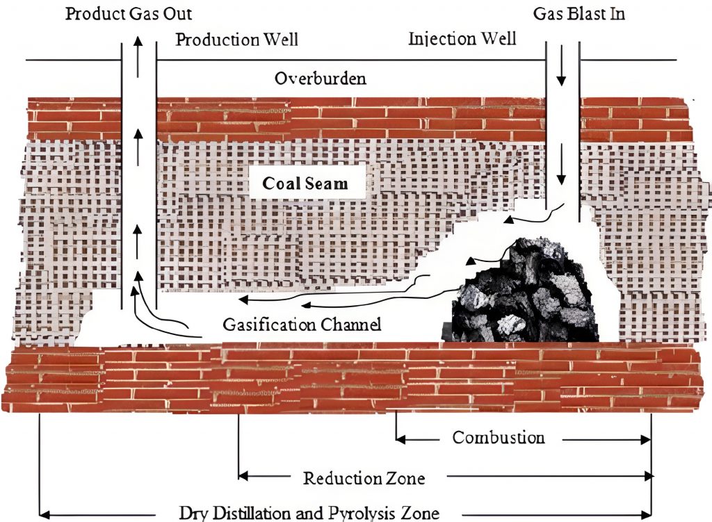
Authors are with John Finlay India Pvt Ltd: Om Prakash- Advisor Coal & Minerals Beneficiation Aadil Keshwani- Managing Director Preamble: We are in an era of depleting resources for petroleum and natural gas due to the rapid growth of our population and demand for gradually improving the quality of our day-to-day life. The invention of Coal Gasification is to make up for the shortage of liquid and gaseous fuels. Coal Gasification is a technical process of converting coal into synthesis gas known as SYNGAS a mixture of carbon monoxide, hydrogen, carbon dioxide, and other minor constituents by reacting the coal with oxygen, steam, and carbon dioxide. This process takes place in a gasifier at a pressure greater than 30 Bar and a temperature typically reaching 1225 Degrees C. TYPICAL INTEGRATED COMBINED CYCLE OF COAL GASIFICATION: The undermentioned typical equipment flow diagram depicts the use of SYNGAS for the generation of electrical power with the following features: Secondly, the hot combustion gas from the gas turbine is sent to the heat recovery steam generator which produces steam, which in turn drives the steam turbine for additional generation of electricity. This demonstrates a typical combined cycle where gas and steam turbines both are in operation for the utilization of gas as well as steam. UNDERGROUND COAL GASIFICATION (UCG): Underground coal gasification is essentially the same chemical conversion process used in surface coal gasification plants to convert solid coal into a mixture of useful gases known as SYNGAS. The main difference is that surface gasification occurs in a manufactured gasifier (reactor) whereas the gasifier for underground is a natural geological formation containing unmined coal. Vertical wells called injection wells and producer wells are drilled into a coal seam and linked together horizontally within the seam. Coal ignition is initiated through the use of an electric coil or gas firing near the surface of the coal seam. A compressed gasification agent (air or oxygen) is pumped into the injection well to allow for the combustion of coal. Combustion produces heat, carbon dioxide, and some SYNGAS through partial combustion. Through a series of chemical reactions involving pressure, heat, and carbon dioxide from combustion, steam (generated from water in the coal) and the carbon from the coal SYNGAS is produced. The gasification channel is normally divided into three zones: – Combustion / Oxidation Zone – Reduction Zone – Dry Distillation & Pyrolysis Zone In the oxidation zone, a multi-phase chemical reaction occurs involving oxygen in the gasification agents and carbon in the coal. The highest temperature occurs in the oxidation zone, due to the large release of energy during the initial reactions. In the reduction zone, the main reactions involve the reduction process. Within the distillation and pyrolysis zone, the coal seam is decomposed into multiple volatiles. Requisite Quality of Coal for Gasification: – Coal having volatile contents of around 35 % is advantageous – The lower rank of coal with a higher % of volatile matter reacts well with oxygen and steam to facilitate the reaction to take place in the gasifier. – Coal with a low moisture % is always beneficial. – The ash % around 30 with infusible ash is always preferred. Hence washed coal is primarily the best for gasification. – Fusible ash tends to serious clinking phenomena in the gasifier and is bound to slag with the lining of the gasifier. For dislodging clinkering, extra force is needed which causes undue loss of carbon in refuse. – Strongly coking coals are not recommended for gasification whereas the use of slightly coking coal in a gasifier is advantageous. Advantages of Underground Coal Gasifier (UCG) Vis-à-vis Overground Gasifier: – UCG offers the potential to use the energy stored in the coal deposits that are uneconomical to mine out the coal by conventional methods. – There is no need to mine out the coal, safety hazards associated with underground coal mining are eliminated. – UCG reduces significant disorders such as surface disturbances, land use conflicts, and avoidance of greenhouse gas production associated with coal mining. – UCG is a carbon capture process as it delivers an enriched CO2 stream suitable for carbon capture and storage. – UCG is a lower carbon-emitting process for power generation when compared to conventional coal-fired power stations. – Capital expenditure for UCG projects can be substantially lower than equivalent surface gasifier projects. Challenges of UCG System Vis-à-vis Overground Gasifier: – High chances of contamination of groundwater in the UCG system. – UCG operation cannot be controlled to the same extent as surface gasifier which poses the risk on account of high temperature and pressure in the cavity. – Some of the coal in UCG may have geologic and hydrologic features that increase environmental risks to unacceptable levels. – The economics of UCG-based power plants are not available as there is no UCG power plant in operation. – UCG carries huge environmental and geological risks. – The void created by UCG may cause significant deformation both in the remaining coal and surrounding rocks. – Heating, quenching, water flux, and potential roof and wall collapse may seriously compromise the integrity of the cavity. These are difficult to predict. – The high ash content of Indian Coal poses significant technical challenges for gasification process. – The UCG system cannot have a facility for washing the coal to meet the ash % requirement. – Underground gasifiers may not be as efficient as overground gasifiers. COAL GASIFICATION PLANTS IN INDIA: India’s foray into Coal Gasification began in the 1960s with the establishment of the Sindri Fertilizer Corporation of India (FCI) Plant. However, significant progress has been sporadic. Presently notable projects include: JINDAL STEEL & POWER LIMITED (JSPL), has been operating a coal-based Direct Reduced Iron (DRI) plant in Angul, Odisha since 2014. BHARAT HEAVY ELECTRICALS LIMITED (BHEL), A pilot plant at Tiruchirappalli generating 6.2 MW, facing challenges with high ash coal. THERMAX A Coal-to-Methanol Pilot Plant in Pune, funded by the Department of Science and Technology under NITI Aayog. TALCHER FERTILIZER LIMITED (TFL),
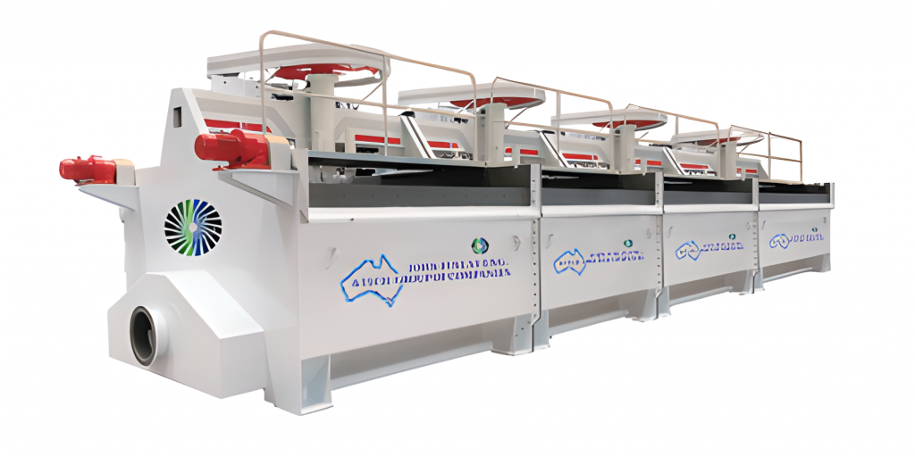
The authors are with John Finlay India Pvt Ltd. Om Prakash- Advisor Coal & Minerals Beneficiation Aadil Keshwani- Managing Director Preamble: Froth Flotation is the most efficient method of beneficiating coal having a particle size below 0.5 mm. Intensive mechanization and poorer quality of seams now left for exploitation, make beneficiation of coal particle size (-) 0.5 coal mm unavoidable. If this fraction is not treated by froth flotation, the losses can be as high as 15-20% of ROM coal. Besides this, the untreated coal fines when mixed with washed coal appreciably increase its ash content. This paper discusses the salient factors affecting the flotation of coal. John Finlay and its partner companies have Flotation Machines well covered in the product range with the following advantages of the Flotation Machine. Advantages: Self-Aeration Mechanical Agitation: Designed specifically for the flotation of (-) 0.5 mm coal, the John Finlay Flotation Machine series utilizes self-aeration mechanical agitation, ensuring efficient and effective processing. No blower is required for forced aeration. Hence, simplified design for achieving optimum performance. Uniform Bubble Distribution: The machine provides a uniform distribution of flotation reagents and then the creation of bubbles, resulting in excellent flotation selectivity and reliable operation, making it ideal for precise coal separation. Low Energy Consumption: Among similar John Finlay, the Flotation Machine series stands out for its low energy consumption and high aeration rate, contributing to cost-effective and sustainable consistent operations and performance. Proven Performance: With over 2,000 units promoted and in operation, is recognized as an ideal upgrade and replacement for older flotation machines, delivering enhanced performance and reliability. Factors Governing the Flotation of Coal: Rank of Coal and Extent of Oxidation: The rank of coal is a very pertinent factor for flotation. Low-volatile coal is easier to float than most high-volatile coal. Anthracite is more difficult to float than highly volatile bituminous coal. Lignite is the least floatable to all coals. Oxidation adversely affects the flotation characteristics of coal. Even easily floatable coal becomes difficult to float post oxidation of coal. If the surface of coal is oxidized, then it behaves like a shale material. With judicious selection and application of flotation reagents, the flotation of oxidized coal can be managed up to a certain extent. Flotation Pulp Preparation: Today mining of coal is fully mechanized and the emphasis is there to raise production as much as possible. In this process of maximizing production, the overburden of mine also becomes a part of production. Due to this flotation feed pulp preparation also varies in nature and proportion as feed coal to washing plant comes from different sources. To feed consistent quality raw coal to the flotation circuit, the facility of blending feed coal from different sources in washery premises must be provided before flotation. Particle Size of Coal in Pulp: The particle size of coal for froth flotation is very important. From laboratory investigation, the established optimum particle sizes for flotation range from 48 mesh to 150 mesh. It is not economical flotation to have a particle size above 0.5 mm. If the recommended particle size range is not fed to flotation, then it affects recovery and flotation time. Pulp Density: If the feed coal size is finer, then 10 % solid by weight is recommended for flotation feed pulp. This is in practice if the coal size is (-) 0.5 mm and below. However, the flotation pulp density range varies from 10 % to 15 % solid by weight. The best way to establish pulp density of flotation is by testing the coal representative coal sample in the washery laboratory flotation machine and then optimizing the pulp density. It is advisable to use these inputs on pulp density for flotation plants. Water Characteristics and pH Level: To achieve an efficient flotation process fresh water and neutralized water will give the optimum performance of flotation process. The best clean coal yield % and optimum recovery % are obtained when water pH ranges from 6.0 to 7.5. Ash % of clean coal will increase with the increase of water pH from the recommended level. Ultra fines in flotation feed pulp will decay the performance of flotation. Quality of Flotation Reagents: Flotation reagents such as Frother, Collector, and Depressant are expensive for the flotation process. The quality of these reagents is to be selected judiciously. The doses of these reagents can be optimized by conducting laboratory tests in a washery laboratory and then with a scale-up factor on doses for flotation plant can be in practice. Reagent doses vary as per feed characteristics of coal for flotation. Normally, conditioning is done with the collector at thicker pulp, 30 % solid by weight. This will optimize the use of collector dose consumption. Postconditioning, the pulp is diluted to 10 % solid by weight in a pulp density adjusting tank and then gravitates to the flotation tank. Flotation at 10 % solid by weight optimizes the yield and recovery from flotation. Frother can be added directly to the first cell of the flotation cell bank. Sometimes, Depressant is used in case of selective flotation by depressing silica and other gangue materials in the feed coal. Conditioning and Flotation Time: The flotation performance depends upon conditioning time and flotation time at respective pulp density. Conditioning time varies from 2 minutes to 4 minutes depending on feed coal characteristics. Flotation time varies from 3 minutes to 5 minutes. This also depends on the feed coal characteristics. Conditioning time and flotation time are prerequisites for flotation and these inputs are decided by laboratory tests in a washery laboratory flotation machine. Scale-up factors on conditioning time and flotation time on laboratory inputs make the basis for commercial flotation plant operation. Flotation Time & Flow Rate: Flotation time and flow rate are interlinked and depend upon flotation operation. For good flotation, sufficient long time is given to the particles to enable them to come in contact with air bubbles. This criterion is important in selecting the number of cells and the bank