John Finlay Group Of Companies

Aadil Keshwani

Intelligent Early Warning Sensors for Mining & Equipment Monitoring | John Finlay Eng

What Early Warning Sensors Catch Before a Failure Costs You a Shift

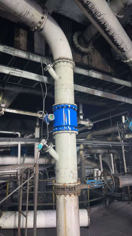
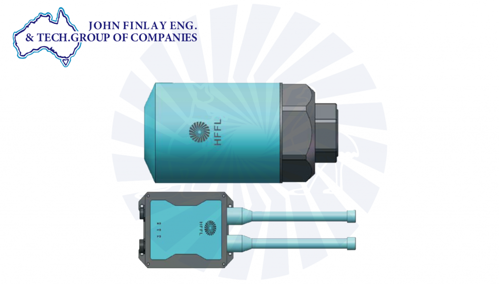
What Early Warning Sensors Catch Before a Failure Costs You a Shift Every rotating piece of equipment in a coal washery will eventually fail. That’s not a controversial statement; it’s physics. The only operational question is whether the equipment warns you in time to act or just stops. That distinction is the entire logic behind early warning sensors, and it’s also the thing most plants get backwards. The instinct is to sensor everything and call it predictive maintenance. The more useful question is narrower: which failure modes on your circuit actually give warnings, and which ones don’t because sensors only help with the first kind? Get that distinction right, and a modest sensor package earns its cost quickly. Get it wrong, and you risk ending up with a dashboard that nobody trusts. Most washeries already run some form of automation for density and process control. Early warning sensing is a natural extension of that same layer rather than a separate system bolted on afterward. The value comes from feeding condition data into a place where a maintenance planner actually looks, not from the sensor hardware itself. What Actually Gives Warning Most mechanical degradation is gradual, which means it leaves a trail before it becomes a failure. A bearing running out its grease life doesn’t seize instantly; it runs hotter and rougher for days or weeks first, showing up in vibration signature and temperature trend before it locks up. A motor drawing more current than its baseline is usually fighting something, a misaligned coupling, a partially blocked screen, or a pump working against a restriction well before that something becomes an unplanned stop. Screen-deck wear thins out gradually and shows up as a slow drift in throughput or product moisture long before a panel actually fails and lets material through unscreened. These are the failure modes early warning sensors are built for: continuous trend data that separates the normal operating range from drifting toward a problem days or weeks ahead of the stop. What early warning sensors can and can’t catch What Doesn’t Not every failure gives that lead time, and it’s worth being honest about which ones don’t, because it changes what you actually protect against with sensors versus what you protect against through design and housekeeping. Tramp metal or oversize rock striking a crusher or screen can introduce sudden mechanical damage with no meaningful trend beforehand; the equipment was fine one minute and damaged the next. Sudden electrical faults, particularly insulation breakdown, often show little warning in the data an ordinary sensor package is watching. Structural fatigue cracks can propagate from undetectable to critical faster than a normal monitoring interval catches, particularly under cyclic loading on screen frames and support structures. The practical implication: a sensor package won’t turn every failure into a scheduled one. What it does is take the failures that were always going to give a warning, which are most of them on a typical washery. and actually put that warning somewhere useful, instead of leaving it as a sound an experienced operator might have caught on a good day and missed on a busy one. What One Unplanned Shift Actually Costs This is the number that gets a requisition signed, and it’s worth working out for your plant rather than borrowing someone else’s figure. Add up lost throughput for the stopped hours at your plant’s tonnes-per-hour rate, valued at your realization price for clean coal. Add the labor cost of the crew standing by or called in for emergency repair, typically at a premium over scheduled maintenance labor. Add expedited parts freight, which, on an unplanned stop, is often several times the cost of the same part ordered on a normal lead time. And if the stop occurs during a period when you’re committed to dispatching tonnage, also include any contractual or goodwill costs that may arise. Run that arithmetic once for your plant, and the business case for early warning tends to write itself because the sensor package and the platform that reads it usually cost a small fraction of a single avoided unplanned shift, not a large one. Avoiding the Opposite Problem The failure mode of the sensor program itself is over-instrumenting without proper thresholds. Sensor every point on the circuit, set every alarm to trigger at the first sign of deviation, and within a few weeks the control room is drowning in alerts that don’t distinguish a genuine early warning from ordinary operating noise. Operators start ignoring the dashboard, which defeats the entire purpose more thoroughly than not having sensors at all. At least without sensors, everyone knows to rely on physical inspection. Thresholds need to be set against each asset’s own baseline, not a generic default, and the alert list needs to stay short enough that every alert on it is one someone will actually act on. Where the Coverage Actually Pays Off Magnetic separators, dense media cyclones, screens and centrifuges each have their own dominant failure modes, but the pattern of gradual degradation with a trend versus sudden and largely trend-free repeats across all of them. Bearing and seal wear, motor loading, and mechanical vibration are the categories where continuous monitoring earns its cost fastest, because they’re both common failure points and reliably gradual ones. We’ve built early warning sensor integration directly into circuit monitoring for centrifuge operations specifically, feeding real-time condition data, not just a snapshot at the next scheduled inspection, into the same automation layer used for density and process control. The value isn’t the sensor itself; it’s having that data land somewhere a maintenance planner actually looks before the trend becomes a stop. Where to Start You don’t need to instrument the whole plant on day one. Start with whichever asset currently causes your longest unplanned stops when it fails; that’s usually where the payback is fastest because the cost of the next unplanned event is the baseline you’re already living with. Build outward from there once the first installation is proving its case in your

What Early Warning Sensors Catch Before a Failure Costs You a Shift Read More »

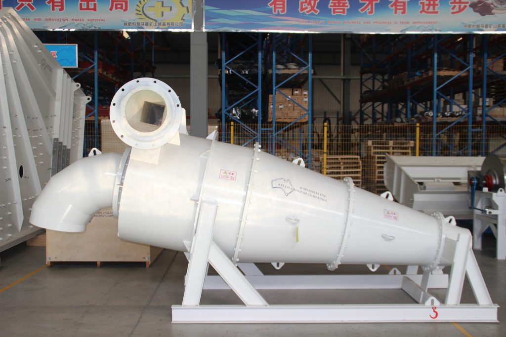
Heavy media cyclone

Cut Point Control in Heavy Media Cyclone Circuits: SG Drift and Correction

Cut Point Control in Heavy Media Cyclone Circuits: SG Drift and Correction Our Dense Media Cyclone product page states a separation efficiency of 95% or better and an Ep of 0.03 or lower. Those numbers are real and achievable, but they describe what a correctly operating cyclone delivers, not a guarantee that holds regardless of how the circuit around it is run. Cut point and Ep both drift in service, and understanding what erodes them is what actually keeps that spec true on your plant, not just on the datasheet. What Ep and Cut Point Actually Measure Cut point d50 is the density at which a particle has an equal chance of reporting to either the clean coal or the reject stream. It’s the number your washability curve is built around, and it determines yield and ash at a given density target. Ep, the probable error, measures how sharp that separation actually is. Take the density at which 75% of particles report to sink and the density at which 25% report to sink, and Ep is half the difference between them. A lower Ep means less material is being misplaced near the cut point of coal that should report to product staying in reject, or higher-ash reject slipping into product. Two circuits can hold the same d50 and produce very different yield and ash outcomes if their Ep values differ. Both numbers matter together. A cyclone holding its design cut point with a widening Ep is still losing yield and ash performance, even though the density target on the gauge hasn’t moved. This is also why Ep alone, without cut point context, can be misleading when comparing circuits. A cyclone running a low cut point with a moderate Ep can still misplace more total tonnage than one running a higher cut point with a genuinely sharp Ep, simply because more of the feed sits near the separating density in the first case. Reading the two numbers together against your actual washability curve tells you whether a given Ep is actually good enough for your coal. What Erodes These Figures in Service Medium SG drift is usually the first point to consider separately against your actual washability curve. Density drift shifts the achieved cut point directly, even when the cyclone itself is mechanically sound. If your medium density isn’t holding at the target you designed the cut point around, no amount of cyclone geometry corrects for it. Medium rheology is the second factor, and it’s driven largely by magnetite granulometry and solids concentration rather than anything happening inside the cyclone body. Poor medium viscosity widens Ep directly because particles don’t respond cleanly to the density gradient the cyclone is trying to create; the medium itself is behaving inconsistently before separation even happens. We go into the specification numbers that hold this steady in our post on magnetite quality and granulometry. Cyclone wear changes the internal geometry the design assumes. Liner wear, particularly at the spigot, gradually alters the flow pattern inside the cone. A worn spigot that’s grown beyond its design diameter changes the underflow density the cyclone can hold, which widens Ep well before the wear becomes visually obvious from outside the unit. Feed pressure outside the design range works against separation from a different angle. Heavy media cyclones are sized for a specific feed head run below it and centrifugal force drops, widening EP run. meaningfully above it, and turbulence increases inside the cone, which also degrades separation sharpness rather than improving it. When spigot capacity is exceeded, roping becomes visible, where the underflow discharge loses its normal spray pattern and instead ropes out in a dense, coherent stream, which is the clearest sign that something upstream has pushed more solids through the spigot than it can properly discharge. Once roping starts, Ep degrades quickly, and it’s usually a downstream symptom of one of the other four causes rather than an independent fault. The vortex finder-to-spigot diameter ratio sits behind several of these symptoms at once. That ratio is what the cyclone’s design assumes when balancing overflow and underflow splits, and it’s fixed by the geometry John Finlay specifies for a given duty. Spigot wear changes the ratio directly. Feed pressure outside the range changes the effective split even with the physical geometry unchanged. Medium rheology issues change how the solids actually distribute across that split regardless of what the ratio nominally is. None of these show up as a single obvious fault; they show up as the ratio no longer doing the job it was sized for, and Ep is usually the first number to reflect that. Five factors that erode separation efficiency in service Diagnosing Which Factor Is Yours Check the medium SG trend first. It’s the cheapest and fastest check, and if density has been drifting, that’s very likely where cut point movement is coming from before anything else needs investigating. Check magnetite specification against your certificate of analysis next, particularly if SG is holding steady but Ep itself has been widening independent of cut point. A circuit can hold its density target while running a medium that’s fundamentally worse at supporting a sharp separation. Inspect spigot diameter directly rather than relying on visual wear alone. A spigot worn a few millimeters beyond spec can shift underflow density meaningfully without looking obviously different from a normal one. Confirm feed pressure against the cyclone’s design specification, since pump wear and circuit changes elsewhere can quietly shift operating pressure away from where the cyclone was sized to run. Watch the underflow discharge for roping during normal operation. If it’s present, treat it as an urgent signal rather than a cosmetic issue; it means the circuit upstream is already overloading the spigot’s capacity. Work through these in order rather than jumping to the one that seems most likely. Because several of these factors interact, worn spigot geometry compounds with feed pressure drift, and off-spec medium compounds with both a plant that assumes it knows the cause and jumps

Cut Point Control in Heavy Media Cyclone Circuits: SG Drift and Correction Read More »

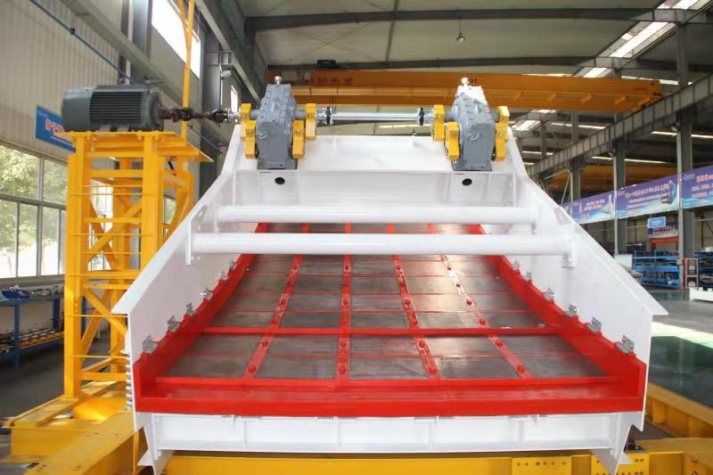
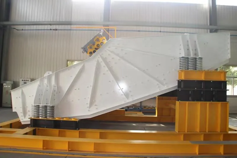
John Finlay banana vibrating screen with curved multi-slope deck on the factory test stand before dispatch to a coal washery

Banana, Horizontal or Inclined? Screen Selection for Coal Washeries

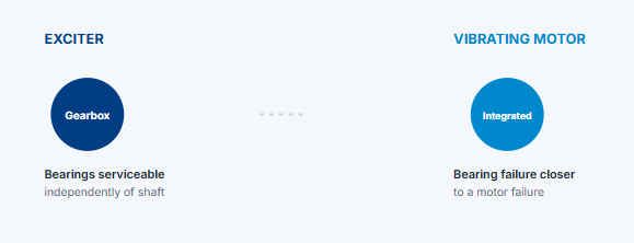
Banana, Horizontal or Inclined? Screen Selection for Coal Washeries Ask three people at a coal washery what a “banana screen” is, and you’ll often get three different answers. Sometimes it’s used as a synonym for “vibrating screen” generally and sometimes as a specific deck geometry, and site documentation doesn’t always agree with itself. Worth settling plainly: the vibrating screen is the equipment family. “Banana,” “horizontal,” and “inclined” describe the deck’s slope profile within that family of three different geometries built for three different jobs, not three different products. Getting this distinction right matters beyond terminology. Specifying the wrong geometry for a given duty shows up as lost capacity or poor screening efficiency that often gets diagnosed as a deck, media, or maintenance problem when the actual mismatch was baked in at the specification stage. What Each Geometry Actually Means An inclined screen runs at a single, constant slope, typically somewhere in the 15 to 25 degree range. Gravity assists material conveying down the slope, which means less reliance on vibration amplitude alone to move material across the deck. It’s mechanically the simplest of the three geometries, and it remains a solid choice for straightforward, lower-tonnage duty where footprint isn’t tightly constrained; a constant slope inherently needs more overall length or height to fit a given screening area. A horizontal screen runs at close to zero slope. With gravity contributing almost nothing to conveying, the screen relies entirely on vibration stroke and frequency to move material across the deck, which means conveying speed and screening performance are both more sensitive to amplitude and stroke settings than on an inclined design. Horizontal screens earn their place where headroom is limited or where the circuit needs a level feed and discharge, a genuine physical constraint the other two geometries don’t solve as cleanly. A banana screen runs at a compound slope steep near the feed end, progressively flattening toward discharge. The steep section handles the wettest, highest-solids part of the feed with the conveying benefit of a steep angle, while the flatter section toward discharge gives fine material more retention time on the deck for effective screening before it reports to undersize. That combination is what lets a banana screen pack more capacity into a given deck width than a constant-angle design running the same total length, which is exactly why banana geometry has become the default choice for high-tonnage, high-moisture Indian coal duty rather than a specialty option. Three deck geometries, one equipment family Why the Naming Gets Confused Part of the confusion is that “vibrating screen” correctly describes all three geometries, so using it as if it names one specific product undersells the choice actually being made. The other part is that manufacturers, including sites like ours, have historically used “banana screen” loosely to mean the whole vibrating screen product line, when it should specifically mean the multi-slope configuration. Going forward, John Finlay’s naming follows the pattern used across our equipment documentation: Vibrating Screen is the product family; Banana, Horizontal, and Inclined are the configurations available within it, specified by deck geometry. Our own manufacturing range confirms this in practice; we build Double Deck Linear Banana and Double Deck Linear Horizontal motorized vibrating screens as distinct configurations on the same underlying platform, not as separate product lines. Buyers researching equipment against this naming should read “banana screen” and “vibrating screen” as describing different levels of the same specification, not competing options. Choosing by Duty, Not by Default Tonnage is the first filter. High-throughput duty, especially on wet Indian coal with a significant near-size fraction, is where banana geometry’s capacity advantage per unit width matters most. Lower-tonnage duty often doesn’t need that advantage, and the mechanical simplicity of an inclined screen can be the more economical choice. Available footprint and headroom is the second filter. A horizontal screen’s near-zero slope needs less vertical clearance for a given screening length than an inclined design running the same length, which matters more on retrofits into an existing structure than on new-build washeries with more design freedom. Feed moisture and near-size content is the third filter, and they interact with both of the above. High-moisture, near-size-heavy feed benefits from the compound slope of a banana screen regardless of tonnage, because the retention time built into the flatter discharge section is what keeps fine, wet material from simply riding across the deck without being properly screened, a problem we cover in more depth in our post on screen blinding and deck media selection, which is really a separate but related question from geometry. Existing circuit constraints matter too. A retrofit into a structure built around one geometry’s footprint often makes switching geometries more expensive than the throughput or efficiency gain justifies, even where a different geometry would technically perform better on a clean-sheet design. Getting the Specification Right None of these three geometries is universally correct. The mistake worth avoiding is picking based on what’s already installed elsewhere in the plant, or on whichever term a previous specification happened to use, rather than on tonnage, footprint, and feed characteristics actually measured for the duty in question. What the Drive Has to Do Differently The exciters driving the screen aren’t interchangeable across geometries either, even when the deck panels themselves could physically bolt onto more than one frame design. A horizontal screen depends entirely on the exciter to generate conveying motion, since gravity isn’t contributing, which typically means running at a higher G-force than an equivalent inclined design needs for the same throughput. A banana screen’s compound slope means the exciter has to deliver consistent stroke and amplitude across a deck that isn’t a single flat plane, which is a different mechanical design problem than driving a constant-angle deck evenly. Specifying screen geometry and exciter sizing together, rather than treating the exciter as an afterthought once the deck geometry is chosen, is where a lot of underperforming installations actually go wrong. A banana screen with an exciter sized for an inclined screen’s duty will often show

Banana, Horizontal or Inclined? Screen Selection for Coal Washeries Read More »

LDC Series intelligent non-nucleonic slurry density meter by John Finlay Engineering for coal washery and mineral processing

Density Control in the Media Loop

Density Control in the Media Loop: What to Measure and Why It Drifts Every dense medium circuit runs on one number more than any other: medium density, usually held to a target specific gravity within a narrow band. Get that number right and the circuit does what it was designed to do. Let it drift, and the effects show up as yield loss and ash penalties before anyone traces the cause back to density control, usually because a plant is checking density less often and less precisely than the number actually needs. It’s also one of the more straightforward instrumentation decisions in a coal washery. Unlike a lot of process changes that require weighing tradeoffs, continuous density measurement at the right points has a fairly direct case: the technology is mature, the installation is routine, and the payback tends to be short once the numbers are actually run for your own plant. Where Density Should Be Measured Most washeries measure density somewhere in the medium loop. Few measure it everywhere the loop actually needs it. Feed density to the cyclone is the measurement that matters most, because it directly sets the cut point. A single continuous reading upstream of the cyclone, rather than a periodic manual sample, is the minimum viable setup, but it only tells you what’s entering the cyclone, not what’s happening to the medium once it’s inside. Underflow and overflow density, measured separately, close the loop. Comparing underflow density against feed density tells you whether the medium is behaving the way the cyclone geometry assumes it should; a widening or narrowing gap between the two is often the earliest sign of a problem elsewhere in the circuit, well before it shows up in yield or ash figures. The dilution water addition point is the fourth place worth instrumenting because that’s where most density corrections actually get made manually, in many plants, based on the same feed density reading the operator is trying to correct in the first place. Why the Number Drifts Density drift usually comes from multiple causes. A few show up repeatedly. Dilution water balance is the most common. Excess water enters the circuit through spray systems, washdown, or upstream process water, diluting the medium; the standard response is to add more magnetite to compensate rather than fixing the water balance itself. We’ve covered this specific failure mode in detail in our post on magnetite consumption benchmarks. Density drift and magnetite consumption often have the same root cause, showing up as two different symptoms. Magnetite quality also drives density drift, independent of water balance. Off-spec magnetite with the wrong SG and wrong particle size changes how much solids loadinis needed to hold a given medium density, sons an operator correcting density based on a fixed magnetite addition rate is chasing a moving target. We go into the specification numbers that matter here in a separate post on magnetite granulometry. Instrument drift itself is worth ruling out before assuming the process is at fault. Density meters need periodic calibration checks; a meter reading consistently high or low by a fixed offset looks identical, on a trend chart, to a genuine process drift. Sensing line blockage or buildup gradually skews readings without an obvious failure event; the meter keeps reporting a number, just not the right one. None of these causes are mutually exclusive, and on plants that have been running the same instrumentation setup for years without review, it’s common to find two of them compounding a water balance issue masked by a meter that’s also drifted out of calibration, for instance, with each one making the other harder to diagnose from the trend data alone. Four points worth measuring in the medium loop What Drift Actually Costs The mechanism is straightforward even when the number is specific to your plant. A shift in medium SG moves the cut point, and moving the cut point either sends coal that should have reported to product into the reject stream, a direct yield loss, or lets higher-density, higher-ash material through to product, showing up as a quality penalty on every tonne shipped rather than a single dramatic event. Because the effect is gradual and distributed across every tonne processed rather than concentrated in an obvious failure, density drift is one of the easier problems to underprice. A 50 kg/m³ drift sustained over a full shift affects every tonne that shift processes, not just a batch. Density drift is also only half of what determines separation performance; the other half is how sharp that separation is at whatever cut point you’re holding, which is a function of the cyclone itself rather than the medium loop. We cover the mechanical side of that in our post on cut point control in heavy media cyclone circuits. The Payback Arithmetic Continuous, correctly located density instrumentation is inexpensive relative to what it protects. The comparison is worth running for your own plant: take your current yield or ash variance attributable to density drift, even a rough estimate from your own QC data; value it against your realization price; and compare that monthly figure against the cost of a properly specified density meter at the points that actually matter. For most plants, the payback period on closing that gap is short, which is part of why this is one of the more straightforward equipment decisions in a coal washery; the case tends to make itself once the numbers are actually run, rather than needing to be argued. How John Finlay Helps Getting density instrumentation right starts with placing it at the points in the loop that actually drive the cut point, not just wherever’s convenient to install. John Finlay’s Intelligent Slurry Density Meters are built for exactly this continuous, real-time monitoring feeding directly into the same automation layer as our Dense Media Cyclones and Magnetic Separators. If you’re not sure where your circuit’s biggest density blind spot is, our engineers can walk your loop with you and point to it directly. Not sure

Density Control in the Media Loop Read More »

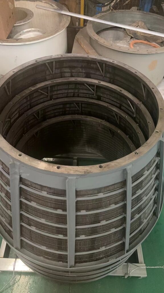
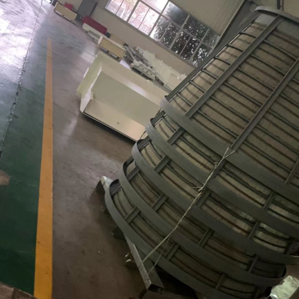
Basket centrifuge screen assembly, coal dewatering, John Finlay manufacturing facility

Tailings Dewatering: Filter Press, Belt Filter Press or Centrifuge?

Tailings Dewatering: Filter Press, Belt Filter Press or Centrifuge? Product moisture is the number that follows a coal washery out the gate. Ash and yield get negotiated in the contract; moisture gets measured on every single truck, and it’s the one quality parameter where the dewatering circuit, not the washing circuit, does almost all of the work. Three technologies do that job on most Indian coal washeries: filter presses, belt filter presses, and centrifuges. They’re not interchangeable. Each one is built for a different fraction of the plant’s solids, and picking the wrong one for a given stream is a common way to end up with a dewatering circuit that’s technically working and still not hitting spec. Feed moisture (avg) % Product moisture (avg) 0 % Reduction, held over 8hr run 7– 0.03 pt Model tested FLL- 1000 WZ What Each Technology Is Actually For Centrifuges handle coarse and fine coal where speed and continuous operation matter. A basket centrifuge spins the wet coal against a slotted or wedge-wire screen basket, using centrifugal force to drive free water through the screen while the solids are held against the wall. It’s a continuous, high-throughput process, which is why it’s the standard choice for dewatering the main clean coal product stream rather than a batch process sitting in the middle of a continuous plant. Filter presses handle the opposite end of the particle size range fine tailings and slurry that centrifuges can’t dewater efficiently, because very fine particles pass through or blind a centrifuge screen faster than they dewater. A plate and frame filter press forces the slurry through filter cloth under pressure, building a solid cake between the plates before the cycle ends and the cake discharges. It’s a batch process by nature, and it’s the technology that makes zero-discharge tailings handling realistic, because the cake it produces is dry enough to stack or truck rather than pump to a pond. Belt filter presses sit between mechanisms, not necessarily based on particle size. Sludge is conditioned with a flocculant, then carried between two porous belts through a series of rollers that apply progressively increasing pressure, squeezing water out continuously as the belts travel. Unlike a filter press, it never stops to discharge a batch; the cake comes off continuously at the end of the belt run. That makes it suited to sites that need continuous tailings dewatering at moderate throughput without the cycle-time constraints of a batch press. Why the Choice Isn’t Interchangeable The three technologies fail differently when applied to the wrong stream, which is usually the fastest way to tell whether a plant has the right one. A centrifuge fed material that’s too fine loses efficiency fast; the fines migrate through the screen slots instead of being retained, so effluent solid losses climb and the dry product moisture that was supposed to drop stays stubbornly high. This scenario is a common cause of centrifuges getting blamed for a moisture problem that actually started upstream, in whatever’s feeding fines into a stream the centrifuge was never sized for. A filter press fed a stream that’s too coarse or too dilute cycles inefficiently. Coarse particles don’t build a cake the way fine slurry does, and a dilute feed just extends cycle time for the same cake yield, cutting the plant’s effective throughput without anyone changing a setpoint. A belt filter press asked to handle a stream with highly variable solids loading struggles to hold a consistent cake because the roller pressure profile is set for a given feed consistency; a sudden slug of solids either overwhelms the belt or passes through under-conditioned. Matching the technology to the actual particle size and throughput profile of the stream being dewatered, rather than to whatever’s already installed, is what most often separates a dewatering circuit that hits spec from one that is fighting its equipment. What Real Performance Looks Like Numbers from an actual plant are more useful here than manufacturer ranges. On an eight-hour test run of a horizontal vibrating basket centrifuge processing combined clean and middling coal, feed moisture averaged 22% and product moisture averaged 15%; a 7 to 8 percentage point reduction held consistently across the full run, with bearing temperatures and vibration amplitude staying within normal operating range throughout. That’s the kind of result that makes a centrifuge the right call for a clean coal stream: consistent, continuous, and stable over a full shift rather than degrading as the run goes on. That same consistency is the test worth applying to any dewatering technology under consideration. A single reliable reading doesn’t confirm a technology choice. A full shift of stable readings does. Wedge-wire screen basket centrifuge, John Finlay manufacturing facility Getting the Most Out of What’s Already Installed Before assuming a technology swap is the answer to a moisture problem, it’s worth checking whether the installed equipment is actually running at its design point. Centrifuge performance is sensitive to the condition of the basket screen. Slots that have worn open lose their retention efficiency long before the basket looks visibly damaged, and vibration amplitude that’s drifted from its set point changes both throughput and product moisture at the same time. The cycle time of the filter press is sensitive to chemical conditioning upstream; a flocculant dose that’s drifted off its optimum will extend every cycle even if the press itself is mechanically sound. The consistency of the belt press cake depends on roller pressure staying matched to actual feed solids, which changes as upstream circuits change. Most moisture complaints labeled as “we need bigger equipment” actually result from mismatched feed conditions and setpoints, rather than any capacity shortfall. Choosing for Your Actual Stream Start with what’s actually in the stream you’re trying to dewater: the particle size distribution, the solids concentration, and how much those vary from shift to shift. A clean coal product stream with coarse-to-mid particle size and continuous flow points toward a centrifuge. A fine tailings stream that needs to go to dry stack rather than

Tailings Dewatering: Filter Press, Belt Filter Press or Centrifuge? Read More »

Coal Washery Magnetic Recovery Equipment Magnetic Separator for Coal Washery

Magnetite Consumption in Dense Medium Circuits: Benchmarks and How to Diagnose Yours

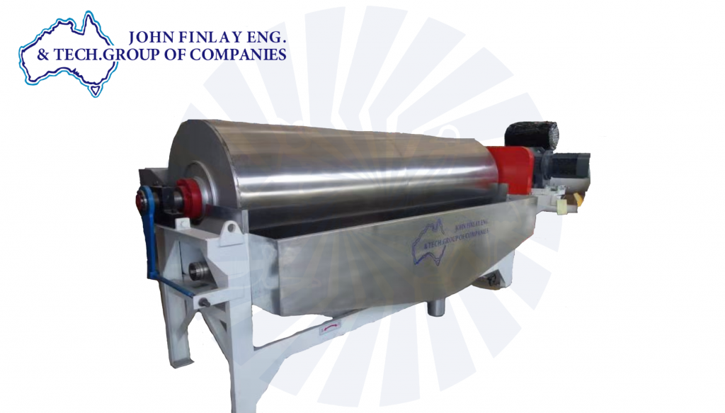
Magnetite Consumption in Dense Medium Circuits: Benchmarks and How to Diagnose Yours Every dense medium circuit consumes magnetite. The number that actually affects your operating cost isn’t whether it consumes magnetite; it’s how much it should consume and whether your circuit’s real figure is close to that or has quietly drifted away from it. For a correctly specified low-intensity wet drum separator, that benchmark sits close to 800 grams of magnetite per tonne of ROM coal washed. That figure comes from our own 2024 technical work on magnetite recovery in Indian coal duty, and it holds for circuits where the drum, the launders and the screens are all doing what they’re designed to do. It isn’t a theoretical minimum reserved for a perfect plant on a good day. Correctly running circuits sit on it. Most plants don’t. Ask five washery managers what their circuit consumes and you’ll usually get five different numbers, most of them well above 800 g/t, and almost none of them broken down by cause. That’s the real problem. Not that consumption is so high that nobody can say why. Magnetite is also one of the few genuinely controllable variable costs in a dense medium circuit. Coal quality is what it is. Throughput is set by the plant’s design and the market. Magnetite consumption, on the other hand, is almost entirely a function of how well the circuit is running, which means it’s one of the fastest places to find real savings without touching capacity or product spec. It matters more in Indian coal duty than the number alone suggests. Higher ash content and larger near-gravity fractions put more physical load through the medium circuit per tonne washed than many imported coals do, which makes the discipline around magnetite recovery worth more here, not less. A circuit that’s leaking magnetite on an easy coal is expensive. The same leak on a difficult Indian coal is worse because the circuit is already working harder to hold separation efficiency. Where The Number Actually Goes The arithmetic is straightforward once you have your number. Take the difference between what your circuit actually consumes and the 800 g/t benchmark, multiply it by tonnes of ROM washed, and multiply it by your delivered magnetite price. That’s what the gap is costing, every month, independent of anything else that might be off in the circuit. It’s rarely one cause on its own. Most circuits we’ve looked at closely turn out to have two or three loss points running at the same time, each one modest by itself, together adding up to a consumption figure that looks unremarkable until it’s actually benchmarked against what the circuit is capable of. A magnetic separator recovering to its rated efficiency is the foundation the rest of this diagnosis depends on. Every other loss point on this list is easier to isolate once you know the drum itself isn’t the source. If your separator hasn’t been checked against rated recovery performance recently, that’s where you should begin. None of this requires shutting the circuit down to find out. A shift-length mass balance, a tailings sample, and an honest look at your density trend will tell you within a day whether you’re close to 800 g/t or carrying a gap worth chasing and roughly which of the five loss points above is the likely cause. Diagnosing Your Own Number Before making any changes to the circuit, please establish your current position. Run a magnetite mass balance over a full shift, comparing the mass of magnetite added to the tonnes of ROM washed in that same shift, rather than relying on monthly purchase records averaged against monthly throughput. Monthly figures smooth out exactly the upsets you’re trying to find. Check the magnetic separator tailings directly. A bucket sample and a hand magnet will tell you, qualitatively and quickly, whether magnetite is riding out with the reject in a way that shouldn’t be happening. If it is, the drum is your starting point for investigation, not the makeup rate. Sample what’s leaving on the product and discard screens, not only what’s leaving in the tailings stream. Carryover on clean coal is invisible unless someone specifically checks for it, and it’s one of the more common blind spots on sites that only monitor the obvious loss points. Track medium density against a setpoint across a full shift rather than relying on a single spot check. A circuit that chronically runs under density and receives fresh magnetite additions has a dilution problem disguised as a magnetite consumption problem. Separate consumption from loss. Some magnetite leaves the circuit because it’s genuinely degraded past the point of recovery for its consumption, and better magnetite quality addresses it. Some leave because a piece of equipment isn’t performing to specification; that’s a loss, and no amount of premium magnetite fixes it. Sites that treat both the same way keep buying their way around mechanical problems. What Closing The Gap Is Worth Before making any changes to the circuit, please establish your current position. Run a magnetite mass balance over a full shift, comparing the mass of magnetite added to the tonnes of ROM washed in that same shift, rather than relying on monthly purchase records averaged against monthly throughput. Monthly figures smooth out exactly the upsets you’re trying to find. Check the magnetic separator tailings directly. A bucket sample and a hand magnet will tell you, qualitatively and quickly, whether magnetite is riding out with the reject in a way that shouldn’t be happening. If it is, the drum is your starting point for investigation, not the makeup rate. Sample what’s leaving on the product and discard screens, not only what’s leaving in the tailings stream. Carryover on clean coal is invisible unless someone specifically checks for it, and it’s one of the more common blind spots on sites that only monitor the obvious loss points. Track medium density against a setpoint across a full shift rather than relying on a single spot check. A circuit

Magnetite Consumption in Dense Medium Circuits: Benchmarks and How to Diagnose Yours Read More »